How Does Lead Came Work? The Anatomy of a Leadlight's Framework
It looks like the simplest part of a leadlight — a humble dark-grey strip — yet it is the window. That strip is lead came (pronounced like "kame"), and it's the material that has been holding coloured glass together for close to a thousand years. But it's not just a spacer. Came is a precisely engineered extrusion with a cross-section that does three structural jobs at once, and it behaves very differently from the glass it grips when the soldering iron comes out.
Let's pull the came apart, see what the H is really for, and — most importantly — talk about the temperatures involved, because that's where most beginners melt their first panel.
What lead came actually is
Lead came is a continuous strip of almost pure lead alloy that's been extruded through a die to give it a very specific cross-section: a capital H when you look down its length. That cross-section is the whole point. It means the strip has two grooves — one on each side of the central spine — and each groove is a channel that holds the raw edge of a piece of glass.
So a single length of came does two things at once: it grips one piece of glass on its left and another on its right, and in doing so it becomes the dark line that separates them. Assemble dozens of these around cut shapes of glass and you've built a panel — a rigid, flexible-in-all-the-right-places framework that can fill a window, a door, or a lamp shade.
The came doesn't glue the panel together. The glass is (usually) a friction-and-setup fit in the channels, and the panel is held rigid by solder joints at every point where two lengths of came meet. That solder, as we'll see, is a much lower-melting alloy than the came itself.
The anatomy of the H
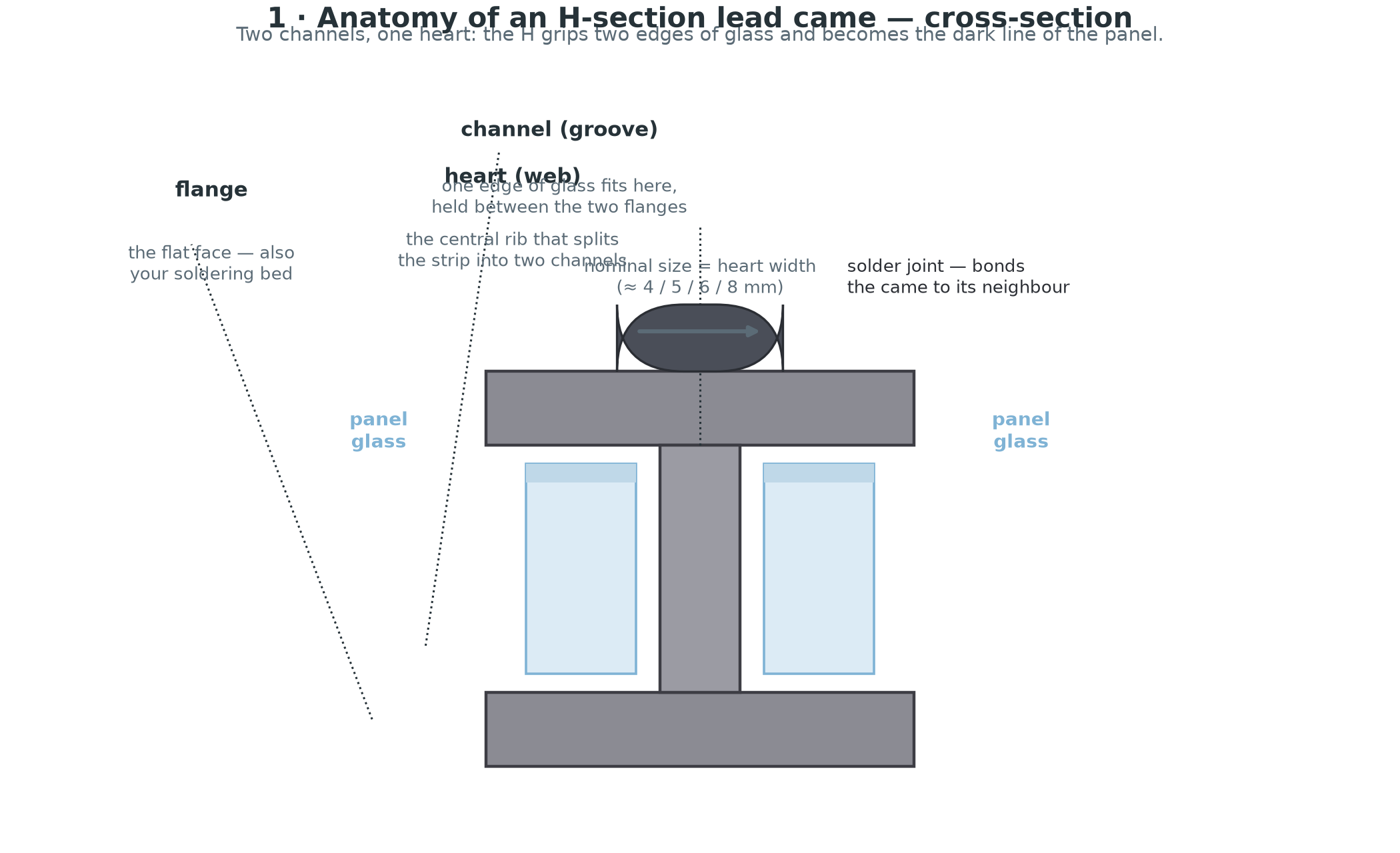
Every lead came — whatever its size or face shape — has the same three parts. Down the middle runs the heart, the central web whose width is what defines the "size" of the came (you'll hear 4 mm, 5 mm, 6 mm, 8 mm heart came, and so on); the wider it is, the bolder the dark line and the more surface a soldered joint has to bite into. Flanking it are the flanges, the two arms of the H, which form the walls of both channels and are what you actually see as the black outline of the design. And between them sit the channels (often called grooves) — the two open slots, one either side of the heart, where the cut edge of a piece of glass slides in. Because the flanges overhang the glass on both faces, the pane is gripped from the front and back, not just at the very edge.
When you see a finished panel face-on, you're looking at the edge of the flanges. The whole strip is only a few millimetres deep in that direction, so the came reads as a slim dark line on the surface — which is exactly what gives a leadlight its distinctive, hand-finished outline.
The H does three jobs at once
That single cross-section is remarkably multi-tasking, and the roles feed off each other.
It grips: each channel holds the raw, cut edge of a pane of glass, which needs no glue to stay put during construction — the geometry (plus a little cement later) keeps it there, and the glass is never drilled, bolted, or otherwise stressed through its own material.
It's also the mechanical skeleton of the panel. The network of came and solder joints is what actually carries the load; a big session is really a series of small panes held in a soft lead framework that absorbs the movement. When an old building settles, when the sun heats the glass, when a door slams — the came flexes and the panel survives instead of shattering.
And it's the solder bed. At every junction the flanges of two, three or even four meeting lengths are laid flat against one another and fused with a single blob of solder. Those joints are what turn the collection of strips into one rigid web — a panel with no solder is just a pile of stems, and the solder is the weld.
That duality — soft enough to flex, yet soldered into a rigid web — is the heart of why lead came has never been bettered for traditional leadlight work.
The material behind the strip
It's worth being precise about what the strip is actually made of, because it explains both how pleasant it is to work and the one big caution.
Commercial lead came is typically 99%+ lead, with a small addition of antimony (and sometimes tiny amounts of tin and copper) added for strength and work-hardening. It's extruded — the hot alloy is forced through a die of the exact H profile, then cooled and drawn down to the final size. The process gives every millimetre of the strip an identical cross-section and a surface that takes solder beautifully without heavy fluxing.
Being dense (about 11.3 g/cm³) and soft is exactly what makes the strip a pleasure to work: it bends and stretches without effort and holds whatever shape you press into it, and unlike springy metal it never springs back, so a panel laid up by eye stays flat and square. The one quirk is that you can work-harden a hinge — unfold the same spot back and forth a few times and it can crack — so don't 0-180° a tight bend repeatedly. It's also heavy, which is a feature: a finished leadlight is genuinely solid, the mass held mostly in the lead rather than the glass.
A tool like a lead vise exists for exactly this reason — its serrated, spring-loaded jaws hold the soft strip firmly without you having to grip it by hand, so you can pull and straighten came precisely as you lay it around a pattern.
The profiles it comes in
"Lead came" is really a family of cross-sections. The two you'll use for almost everything are the H-section (interior lines) and the U-channel (the perimeter of the panel), and they come in a range of sizes and face shapes.
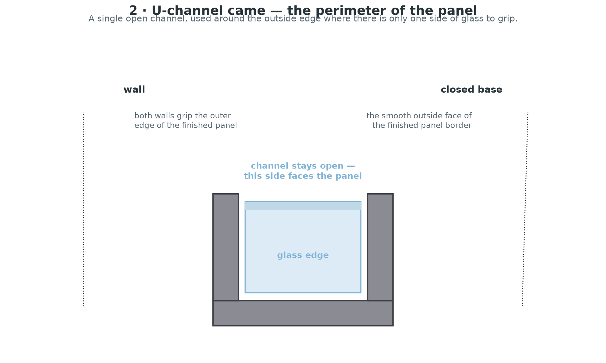
H-section came is the workhorse: each length carries two channels, so it forms every interior line where there's glass on both sides. Within the H family the choice is face shape and size. A flat H has square, crisp flanges — the slim default for fine, detailed work. A round (or domed) H carries a soft, curved face, the heavier-looking line you see on classic leadlight doors and panels. And a heavy H pushes the heart and channels up, which is what you reach for with thick glass — bevels, 6 mm slabs — and bold geometric designs that want a chunky dark line.
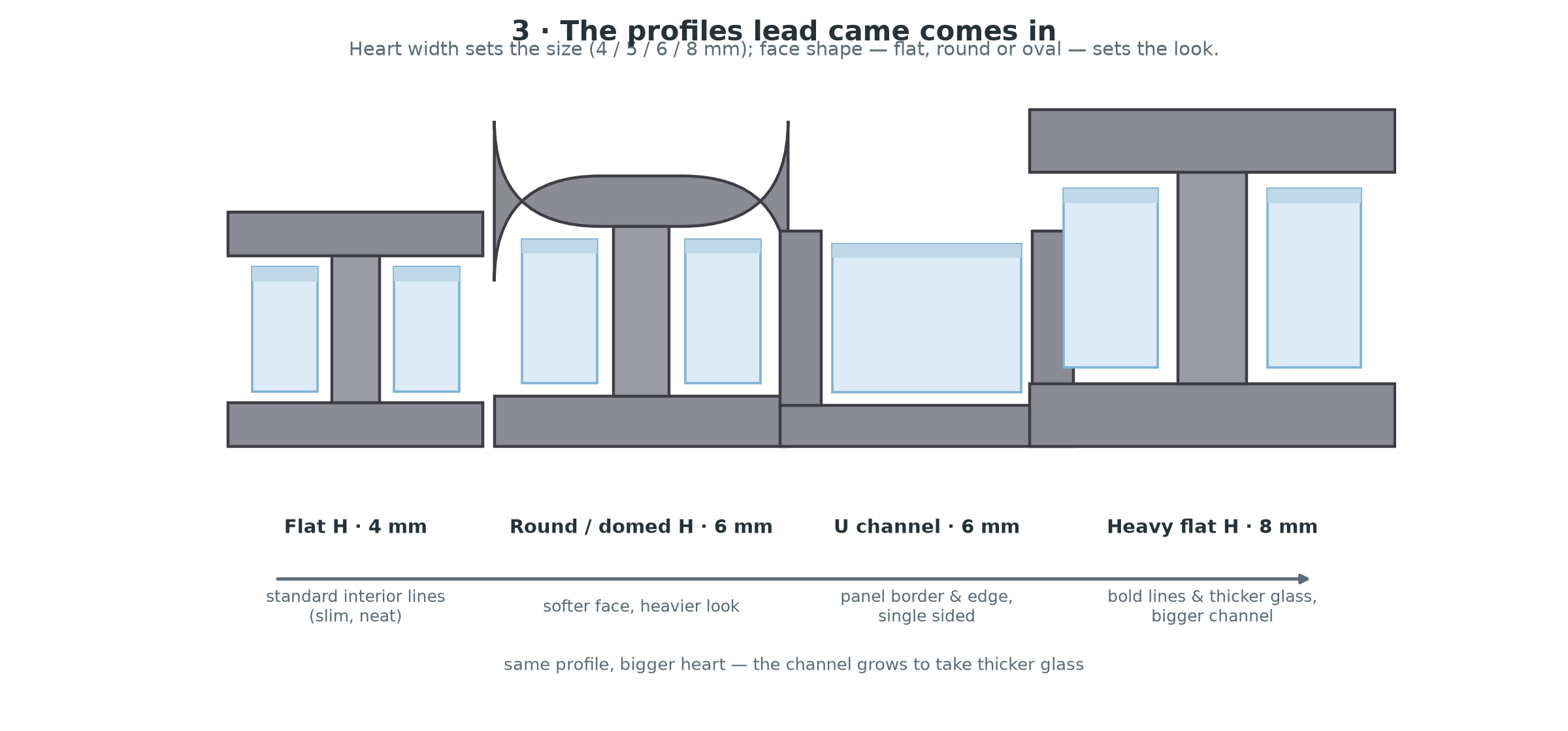
U-channel came — a single open channel, shaped like a "U". It's used on the outside of the whole panel, where there's only one edge of glass to grip and the other side must be smooth. It forms the border that frames the design.
This is the "edge came" — unlike the H, it has room for glass on only one side of the came. There's no second channel because there's no second pane out past the window frame, just the solid, closed back of the U facing outward. If you ever need edge came for an odd job and only have H on hand, the traditional shortcut is to split an H down one flange with a knife — cutting along the heart leaves you with two single-channel strips, one for each straight edge of the panel.
Oval / round came — decorative versions with a rounded or oval outline, used for accent borders and around lamps.
Sizing in the real world
The size you quote is the width of the heart — the web you see as the dark line. Common stock runs roughly 4, 5, 6 and 8 mm (with larger sizes for architectural work). Two considerations drive the choice. The channel has to be deep enough to swallow your glass: 3 mm glass sits comfortably in a standard 4–6 mm came, while thicker stock — bevel clusters, 6 mm slabs, some textured glass — needs a bigger heart with a correspondingly deeper channel. And weight of line matters too: step up a size and the same pattern suddenly reads far bolder, so the classic approach is a slim flat H for fine detail, a round H for general work, and a bigger H for chunky panels.
A quick rule of thumb for building a panel:
| What you're framing | Came profile |
|---|---|
| Interior lines of a small, detailed panel | 4 mm flat H |
| General panel interior | 5–6 mm round or flat H |
| Panel perimeter / border | U-channel (match the glass you've used) |
| Thick glass or bold geometry | 6–8 mm heavy H |
Pattern scissors earn their keep here: the 1.8 mm spacing between the blades is exactly the allowance for the came, so the paper pattern you cut already includes the extra few millimetres of lead that will sit in every gap. Cut the pattern with ordinary scissors and your finished panel comes out a smidge smaller than you drew it.
Soldering: the temperature that matters — be careful
This is the one place novices melt their work, so it's worth being very specific about numbers.
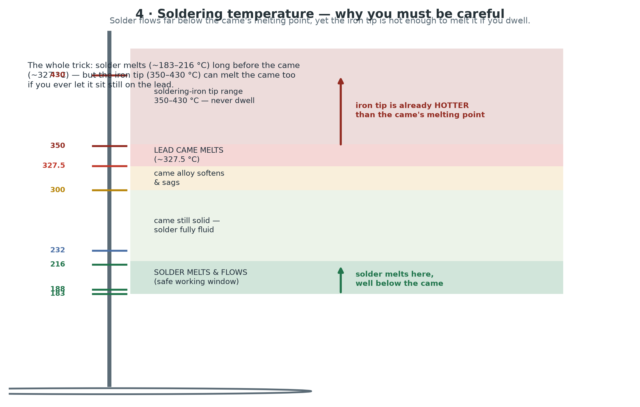
Solder is a lead–tin alloy, and it's engineered to melt long before the came does. The two most common body solders for lead came are 60/40 (60% tin, 40% lead — solidus ~183 °C, fully liquid ~188 °C) and, traditionally, 50/50 (melts over the range ~183–216 °C). Lead-free solders (tin/copper/silver) flow higher, roughly 217–227 °C. Pure tin itself melts at 231.9 °C.
The came, by contrast, melts around 300–327 °C — pure lead at 327.5 °C, and the 99% lead came alloy slightly below that because of its alloying additions (antimony depresses the melting range a little).
Here's the measure that matters: a typical soldering iron tip runs at 350–430 °C. That is already above the melting point of the lead came itself.
Why panels don't melt — and when they do
The panel survives because the solder melts first. When you touch the iron to a joint:
- The flux activates and the solder flows at ~183–216 °C, wetting both flanges.
- Because lead is an excellent heat sink, that heat spreads fast into the came and the surrounding iron — the spot you're soldering usually stays just below the came's melting point.
- You lift the iron. The solder solidifies in a second. Done.
But that safety margin is thin, and it disappears the moment the iron stops moving:
The cardinal rule is never let the flat of a hot iron sit on the came — resting one at 380 °C on a 327 °C metal for more than a second or two starts melting the lead: the flange softens, the channel slumps, the adjacent glass drops, and you've ruined the joint and probably scorched the glass edge. Instead, keep the iron moving — a few seconds of contact per joint, and if the solder isn't flowing, add more flux rather than holding on longer. You can also mind the temperature dial: there's no need for a 450 °C iron on came; a regulated iron in the mid-300s °C with a properly tinned tip solders beautifully and leaves far less margin for error. And don't over-solder — a big molten blob holds heat and takes long to cool, whereas a neat joint sets in a blink and never threatens the came.
The practical takeaway: the solder melts long before the came, but the iron alone is hot enough to melt the came — so it's your technique, not the metal, that protects the panel. Move, don't dwell, and let the solder, not the iron, do the melting.
The same caution belongs in your habits, not just your hands
Practically, lead and lead-based solder are on everything you've handled all session, so wash your hands thoroughly before eating — the real hazard is fine dust and residue, not the solid bar. Work somewhere ventilated: modern lead-free solder removes the fume worry from soldering, but the came itself is still largely lead, and cementing and scrubbing can raise dust, so keep the bench wiped down and don't eat over it.
You'll hear purists argue about tin content in solder — higher tin flows shiner and joints look brighter and stand proud, lower tin gives a duller, more traditional finish. Either melts well below the came, so choose for finish, not for safety margin.
Cementing — the quieter second job of the came
Once soldered, a panel's channels are cemented with a linseed-oil-based glazing putty. The cement is pushed into the channels under the flanges and over the glass edges — a little chalk or whiting is added for body. Its jobs are quiet but essential: it locks the glass so it can't rattle or creep in its channel, it weatherproofs the narrow gap where water could otherwise get behind the pane, and it stabilises the whole structure, setting firm over weeks and taking load off the pure solder-tension web.
This is why a plastic burnisher is in every glass artist's kit — "opening" the channels before assembly, and pressing cement right down under the flanges afterward, is exactly what its slim wedge end is shaped for.
Putting it together
- Cut your pattern with pattern scissors so every line allows for the came.
- Lay came around the outside first (U-channel for the border), then work in.
- Set each piece of glass into the channels — the H grips one edge either side.
- Pull, stretch, and straighten the came as you go, using a lead vise to hold slack firmly.
- Solder every junction — iron moving, solder flowing at ~183–216 °C, never letting the iron dwell on the came.
- Flip and solder the rear face, then cement, scrub, and blacken.
Lead came is a beautiful piece of engineering hiding in plain sight: an extrusion shaped like a single letter that grips two panes at once, forms the skeleton of the whole panel, and melts low enough to worry about — but not low enough to beat you, if you respect the iron.
Ready to start a leadlight? Browse the shop →
Cross-section and temperature diagrams generated with matplotlib. Photographs of real came to come.